

What Equipment At The Cable Service Provider Office Connects The Office To The Subscriber Locations?
Table Of Contents
Product Overview
Overview of the Cisco uBR925 Cable Access Router
Introduction
Bridging Operations
Routing Operations
Voice Operations
Features
Basic Features
Configuration Options
Management Capabilities
Physical Description
LED Descriptions
Data Ports
Voice Ports
Power Supply
Functional Overview
Initial Power On and Provisioning
Initial Power On Sequence
Provisioning Prerequisites
Upgrading the Software Image
Data Operations
Downstream Transmissions
Upstream Transmissions
Security
Voice Operations
Product Overview
This chapter describes the Cisco uBR925 cable access router and its interaction with the Cable Modem Termination System (CMTS)—the cable system headend equipment that provides Internet (TCP/IP) connectivity for subscribers over the cable broadband infrastructure. The chapter provides physical and functional overviews of the Cisco uBR925 cable access router and its supported operating modes.
This chapter provides the following information about the Cisco uBR925 cable access router:
•![]() Overview of the Cisco uBR925 Cable Access Router
Overview of the Cisco uBR925 Cable Access Router
•![]() Physical Description
Physical Description
•![]() Functional Overview
Functional Overview
For information on configuring the Cisco uBR925 cable access router, see the Cisco uBR905/uBR925 Cable Access Router Software Configuration Guide, available on CCO and the Documentation CD-ROM.
Overview of the Cisco uBR925 Cable Access Router
This section provides an overview of the Cisco uBR925 cable access router, its hardware, and its basic operation:
•![]() Introduction
Introduction
•![]() Features
Features
Introduction
The Cisco uBR925 cable access router functions at its most basic level as a cable modem—a modulator/demodulator that provides high-speed network access on the cable television system to residential and small office/home office (SOHO) subscribers. The Cisco uBR925 cable access router uses the cable system's existing physical plant to provide Internet and other wide area network (WAN) connectivity over the service provider's Hybrid/Fiber Coax (HFC) cable system.
The router is based on the Data-over-Cable Service Interface Specifications (DOCSIS), a standard developed with service providers to ensure that any DOCSIS-certified cable modem can interoperate with any bidirectional, DOCSIS-qualified CMTS. The DOCSIS standard also sets required levels of performance and reliability for the cable network.
The Cisco uBR925 cable access router can connect to a PC through either its Ethernet hub ports or through its Universal Serial Bus (USB) port. If supported by the service provider, the router can connect more than one PC using both types of connections.

Note ![]() Information about DOCSIS requirements and current specifications are available at the CableLabs web site at http://www.cablelabs.com.
Information about DOCSIS requirements and current specifications are available at the CableLabs web site at http://www.cablelabs.com.
In this mode, the router operates as an IP bridge between the cable, Ethernet, and USB interfaces, by performing the following functions:
•![]() Traffic from the cable interface is sent to the Ethernet and USB ports for transmission to the connected CPE devices.
Traffic from the cable interface is sent to the Ethernet and USB ports for transmission to the connected CPE devices.
•![]() Traffic from the Ethernet and USB ports is sent to the cable interface for transmission to the Internet (or other network) by the gateway at the headend.
Traffic from the Ethernet and USB ports is sent to the cable interface for transmission to the Internet (or other network) by the gateway at the headend.
In addition to providing DOCSIS connectivity, the Cisco uBR925 cable access router can also function as an IP router, using static routes and the RIPv2 routing protocol. When operating in routing mode, the Cisco uBR925 cable access router can optionally provide advanced data and routing features, such as IPsec encryption.
In both bridging and routing modes, the router can connect one or more computers to the Internet over the HFC cable system. Subscribers can use the Cisco uBR925 cable access router to create high-speed, permanent access to the Internet, without the need for telco-based services such as leased lines.
Based on the feature licenses that your company has purchased, you can download other Cisco IOS images from the Cisco.com website. These images provide additional functionality such as advanced routing capabilities, firewall protection, and high-security encryption.
For most residential applications that involve basic Internet access, the Cisco uBR925 cable access router is configured as a bridge. For residential and SOHO applications that involve special feature sets such as the firewall feature set, or that include connection to an existing network at the site, the Cisco uBR925 cable access router is configured as a router.
Bridging and routing operations are summarized in the following sections.
Bridging Operations
When acting as a DOCSIS-compliant cable modem, the Cisco uBR925 cable access router provides DOCSIS IP bridging for one or more PCs and other customer premises equipment (CPE). The router ships from the factory with a Cisco IOS software image stored in nonvolatile Flash memory that supports DOCSIS-compliant bridging data operations.
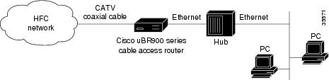
When installed and configured as a bridge, the Ethernet hub ports at the rear of the Cisco uBR925 cable access router can be connected directly to PCs at the subscriber site. A maximum of four PCs can be directly connected to the router's hub ports, or a maximum of 254 PCs can be connected if one of the four Ethernet hub ports is connected to a standard 10BaseT Ethernet hub, which then connects to additional computers (or hubs) at the site.
Regardless of the configuration, Cisco IOS software treats all four Ethernet hub ports as one Ethernet interface. See Figure 1-1 for a typical configuration using the Ethernet ports.
Figure 1-1 Cisco uBR925 Cable Access Router in a Bridging Configuration
A PC can also be connected to the USB port at the rear of the Cisco uBR925 cable access router. Only one PC can be connected using the USB port, but both the USB and Ethernet ports can be used at the same time, if supported by the service provider.
Note ![]() For better network performance, Cisco recommends a maximum limit of 16 CPE devices in either bridging or routing mode. The service provider can also set a different limit by changing the MAX CPE parameter in the DOCSIS configuration file—the default MAX CPE value is one CPE device.
For better network performance, Cisco recommends a maximum limit of 16 CPE devices in either bridging or routing mode. The service provider can also set a different limit by changing the MAX CPE parameter in the DOCSIS configuration file—the default MAX CPE value is one CPE device.
Routing Operations
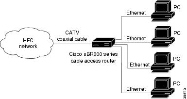
When configured as a router, the Cisco uBR925 cable access router can be connected directly to four PCs using the Ethernet hub ports at the rear of the router. One of the four Ethernet hub ports can also be connected to a standard 10BaseT Ethernet hub, which then connects additional computers or Ethernet devices at the site to a local area network (LAN). (See Figure 1-2.)
Figure 1-2 Cisco uBR925 Cable Access Router in a Routing Configuration
The USB port can also be used to connect one PC in routing mode. In this configuration, the USB interface acts as a separately routable interface. If supported by the service provider, this allows the Cisco uBR925 cable access router to use both the Ethernet and USB interfaces as independently routable interfaces.
In routing mode, the Cisco uBR925 cable access router is typically configured to use the IP address of the headend router as its default IP gateway. Routing mode does not have a maximum limitation on the number of CPE devices, as is the case in bridging mode. However, the CMTS can still limit the number of CPE devices by limiting the number of IP addresses that any particular cable modem can provide services for. If this is the case, the Cisco uBR925 cable access router can use NAT/PAT translations to use one IP address for multiple CPE devices.
Voice Operations
The Cisco uBR925 cable access router supports Voice over IP (VoIP), which transmits voice, modem, and fax calls over a TCP/IP network such as the Internet. Depending on the services purchased from the cable service provider, subscribers can place and receive calls without using the local exchange carrier.
The cable access router contains two voice ports, which support two simultaneous voice, modem, and fax calls. You can connect two single-line telephones, modems, or fax devices to each of the voice ports, or you can connect a dual-line telephone to the first voice port.
Subscribers can connect standard analog telephones, modems, and fax devices to the Cisco uBR925 cable access router; IP telephones are not required. Depending on the voice network set up by the service provider, subscribers can place calls to numbers that are in the existing telco network; the called party does not have to be using VoIP telephone service.
Note ![]() The Cisco uBR925 cable access router provides FXS (Foreign Exchange Station) services and supports analog phones, fax devices, and modems. The Cisco uBR925 cable access router's voice ports do not support devices requiring Foreign Exchange Office (FXO) services, such as PBX devices.
The Cisco uBR925 cable access router provides FXS (Foreign Exchange Station) services and supports analog phones, fax devices, and modems. The Cisco uBR925 cable access router's voice ports do not support devices requiring Foreign Exchange Office (FXO) services, such as PBX devices.
You can also connect multiple telephones, modems, and fax devices to a single voice line. However, each multiple device acts as an extension to that voice line, and only one call at a time can be made per voice line. The Cisco uBR925 cable access router supports multiple devices per voice line. However, the total REN value for all devices must not exceed the maximum number given in "Technical Specifications."
Note ![]() The REN value is a measure of the AC load that the device places on a voice line and is typically listed on each device. If too many devices are connected to the line, the telephones might not ring properly, and you might have difficulty completing telephone calls.
The REN value is a measure of the AC load that the device places on a voice line and is typically listed on each device. If too many devices are connected to the line, the telephones might not ring properly, and you might have difficulty completing telephone calls.
Telephones at each subscriber site must support touch-tone dialing; rotary dialing is not supported. Special telephone features such as call waiting, forwarding, and conferencing are supported only if using a Cisco IOS image that supports those particular features.
Note ![]() fax devices—standard Group III and computer-based Group III machines up to 14,400 baud—are supported.
fax devices—standard Group III and computer-based Group III machines up to 14,400 baud—are supported.

Caution ![]() In certain countries, the provisioning of voice telephony over the Internet or use of these products may be prohibited and subject to laws, regulations, or licenses, including requirements applicable to the use of the products under telecommunications and other laws and regulations. The customer must comply with all such applicable laws in the country where the customer intends to use the product.
In certain countries, the provisioning of voice telephony over the Internet or use of these products may be prohibited and subject to laws, regulations, or licenses, including requirements applicable to the use of the products under telecommunications and other laws and regulations. The customer must comply with all such applicable laws in the country where the customer intends to use the product.
Features
This section provides an overview of the Cisco uBR925 cable access router's features, and is divided into the following categories:
•![]() Basic Features
Basic Features
•![]() Configuration Options
Configuration Options
•![]() Management Capabilities
Management Capabilities
Basic Features
The Cisco uBR925 cable access router provides the following features:
•![]() DOCSIS-compliant cable modem that delivers peak data rates of 44 Mbps downstream and 10 Mbps upstream for an always-on connection.
DOCSIS-compliant cable modem that delivers peak data rates of 44 Mbps downstream and 10 Mbps upstream for an always-on connection.
•![]() Support for 6 MHz downstream and 200K through 3200 KHz upstream cable channel bandwidth.
Support for 6 MHz downstream and 200K through 3200 KHz upstream cable channel bandwidth.
•![]() Comprehensive power-up and CMTS-initiated diagnostic features.
Comprehensive power-up and CMTS-initiated diagnostic features.
•![]() Continuous downstream and upstream channel performance and impairment information gathering.
Continuous downstream and upstream channel performance and impairment information gathering.
•![]() IP bridging and IP routing using Cisco IOS software.
IP bridging and IP routing using Cisco IOS software.
•![]() Other feature sets, such as IPsec encryption or firewall protection, are optionally available, depending on the Cisco IOS image being used.
Other feature sets, such as IPsec encryption or firewall protection, are optionally available, depending on the Cisco IOS image being used.
•![]() Support for an unlimited number of PC and other CPE devices in routing mode (subject to the limits imposed by the service provider).
Support for an unlimited number of PC and other CPE devices in routing mode (subject to the limits imposed by the service provider).
•![]() Coaxial cable (F-connector) interface.
Coaxial cable (F-connector) interface.
•![]() Four-port 10Base T Ethernet hub interface.
Four-port 10Base T Ethernet hub interface.
•![]() Universal Serial Bus (USB) type "B" (device) interface.
Universal Serial Bus (USB) type "B" (device) interface.
•![]() Two Voice over IP (VoIP) ports that support analog telephone, fax, or modem devices.
Two Voice over IP (VoIP) ports that support analog telephone, fax, or modem devices.
•![]() Support for unicast, broadcast, and multicast IP packets.
Support for unicast, broadcast, and multicast IP packets.
•![]() Automatic configuration and piracy control provided by:
Automatic configuration and piracy control provided by:
–![]() Automatically downloading a DOCSIS configuration file from the headend to configure itself for operation on the cable network.
Automatically downloading a DOCSIS configuration file from the headend to configure itself for operation on the cable network.
–![]() Running resident Cisco IOS image or optionally downloading a new Cisco IOS image as directed by the CMTS.
Running resident Cisco IOS image or optionally downloading a new Cisco IOS image as directed by the CMTS.
–![]() Optionally downloading a Cisco IOS configuration file to configure advanced feature sets.
Optionally downloading a Cisco IOS configuration file to configure advanced feature sets.
•![]() Support for remote software upgrades without requiring a visit by a cable technician.
Support for remote software upgrades without requiring a visit by a cable technician.
•![]() Security on the cable interface is provided by the DOCSIS Baseline Privacy Interface (BPI):
Security on the cable interface is provided by the DOCSIS Baseline Privacy Interface (BPI):
–![]() 40-bit or 56-bit DES encryption.
40-bit or 56-bit DES encryption.
–![]() Automatically established when enabled and supported by both the router and CMTS.
Automatically established when enabled and supported by both the router and CMTS.
–![]() Encrypts all Ethernet packets transported on the cable interface between the router and CMTS.
Encrypts all Ethernet packets transported on the cable interface between the router and CMTS.
•![]() Optional end-to-end security provided by IPsec encryption:
Optional end-to-end security provided by IPsec encryption:
–![]() IPsec hardware accelerator provides high-performance encryption without affecting overall throughput.
IPsec hardware accelerator provides high-performance encryption without affecting overall throughput.
–![]() Provides the capability to create secure virtual private networks (VPNs) across unprotected networks such as the Internet.
Provides the capability to create secure virtual private networks (VPNs) across unprotected networks such as the Internet.
–![]() Encrypts all or part of the traffic sent between CPE devices and a destination IPsec peer router or gateway.
Encrypts all or part of the traffic sent between CPE devices and a destination IPsec peer router or gateway.
–![]() 56-bit DES encryption and 168-bit 3DES high-security encryption, depending on the capabilities of the Cisco IOS image being used.
56-bit DES encryption and 168-bit 3DES high-security encryption, depending on the capabilities of the Cisco IOS image being used.
–![]() Supports symmetric key encryption, public key encryption, authentication, and data compression in hardware.
Supports symmetric key encryption, public key encryption, authentication, and data compression in hardware.
–![]() Key management includes support for the IKE protocol, including a true hardware random-number generator, as well as RSA, Diffie-Hellman, and DSA key setup.
Key management includes support for the IKE protocol, including a true hardware random-number generator, as well as RSA, Diffie-Hellman, and DSA key setup.
–![]() Authentication methods include the HMAC SHA-1 and HMAC MD5 authentication algorithms.
Authentication methods include the HMAC SHA-1 and HMAC MD5 authentication algorithms.
•![]() Variable-length packet cable Media Access Control (MAC) transport layer.
Variable-length packet cable Media Access Control (MAC) transport layer.
•![]() Contention-based and reservation-based upstream transmission.
Contention-based and reservation-based upstream transmission.
•![]() Remote-Diagnostic Features—Delivers increased reliability and reduced maintenance costs.
Remote-Diagnostic Features—Delivers increased reliability and reduced maintenance costs.
•![]() Supports the use of commercial security products, such as Kensington-compatible lock and cable devices, that attach to the router to prevent theft in small office applications.
Supports the use of commercial security products, such as Kensington-compatible lock and cable devices, that attach to the router to prevent theft in small office applications.
Note ![]() Cisco does not supply Kensington-compatible security products.
Cisco does not supply Kensington-compatible security products.
Configuration Options
•![]() Automatically download a DOCSIS configuration file from the cable interface, which automatically configures the router for communication with the CMTS and cable network.
Automatically download a DOCSIS configuration file from the cable interface, which automatically configures the router for communication with the CMTS and cable network.
•![]() Optionally download a new Cisco IOS software image to easily upgrade its capabilities without requiring an onsite visit from a service provider technician.
Optionally download a new Cisco IOS software image to easily upgrade its capabilities without requiring an onsite visit from a service provider technician.
•![]() Optionally download a Cisco IOS configuration file that configures the unit for advanced features such as IPsec encryption.
Optionally download a Cisco IOS configuration file that configures the unit for advanced features such as IPsec encryption.
Management Capabilities
•![]() Can be managed by the SNMP protocol, through the command-line interface (CLI), which is available through the console port or Telnet access, and by using the built-in web interface. Management and provisioning can also be done using Cisco's network products, such as Cisco Network Registrar, Cisco Cable Manager, and Cisco Subscriber Registration Center.
Can be managed by the SNMP protocol, through the command-line interface (CLI), which is available through the console port or Telnet access, and by using the built-in web interface. Management and provisioning can also be done using Cisco's network products, such as Cisco Network Registrar, Cisco Cable Manager, and Cisco Subscriber Registration Center.
•![]() SNMP support includes support for the SNMPv1, SNMPv2c, and SNMPv3 versions of the protocol.
SNMP support includes support for the SNMPv1, SNMPv2c, and SNMPv3 versions of the protocol.
•![]() Special web interface is automatically activated when the cable interface is not operational, which allows users to easily supply configuration and status information to support engineers.
Special web interface is automatically activated when the cable interface is not operational, which allows users to easily supply configuration and status information to support engineers.
•![]() LEDs on the front panel provide run-time status information on the Cisco uBR925 cable access router, its interfaces, and its links.
LEDs on the front panel provide run-time status information on the Cisco uBR925 cable access router, its interfaces, and its links.
Physical Description
The Cisco uBR925 cable access router is a compact, easy-to-install device that contains the following:
•![]() A single F-connector interface to the cable system.
A single F-connector interface to the cable system.
•![]() Four RJ-45 (10BaseT Ethernet) hub ports to connect a maximum of four computers directly to the Ethernet hub ports at the rear of the unit (depending on the Cisco IOS release). Alternatively, one of the four ports can connect to an Ethernet hub, which then can connect additional computers or devices at the site. (The actual number of supported CPE devices depends on the Cisco IOS release; see the "Bridging Operations" section for details.)
Four RJ-45 (10BaseT Ethernet) hub ports to connect a maximum of four computers directly to the Ethernet hub ports at the rear of the unit (depending on the Cisco IOS release). Alternatively, one of the four ports can connect to an Ethernet hub, which then can connect additional computers or devices at the site. (The actual number of supported CPE devices depends on the Cisco IOS release; see the "Bridging Operations" section for details.)
•![]() One USB port (type "B" connector) to connect a PC directly to the cable access router.
One USB port (type "B" connector) to connect a PC directly to the cable access router.
•![]() Two RJ-11 Foreign Exchange Station (FXS) ports to connect telephones and fax devices to the cable system and IP backbone. The cable access router ships from the Cisco factory with the voice ports disabled.
Two RJ-11 Foreign Exchange Station (FXS) ports to connect telephones and fax devices to the cable system and IP backbone. The cable access router ships from the Cisco factory with the voice ports disabled.
•![]() One RJ-45 console port (optional) to connect to a laptop PC or console terminal when locally configuring the cable access router.
One RJ-45 console port (optional) to connect to a laptop PC or console terminal when locally configuring the cable access router.
Note ![]() The Cisco uBR925 cable access router ships from the Cisco factory with the console port enabled. By default, downloading a Cisco IOS configuration file disables the console port and erases all previously saved configurations, which prohibits configuration access at the remote site.
The Cisco uBR925 cable access router ships from the Cisco factory with the console port enabled. By default, downloading a Cisco IOS configuration file disables the console port and erases all previously saved configurations, which prohibits configuration access at the remote site.
Figure 1-3 depicts the front of the Cisco uBR925 cable access router. Figure 1-4 shows the rear of the unit.
Figure 1-3 Cisco uBR925 Cable Access Router Front View
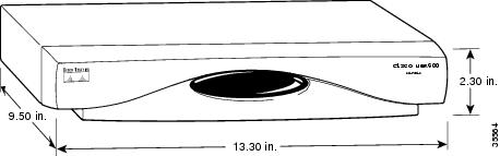
Figure 1-4 Cisco uBR925 Cable Access Router Rear View
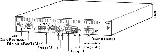
The Cisco uBR925 cable access router is designed to work with commercial security products, such as Kensington-compatible lock and cable devices, that attach to the router to prevent theft in small office applications. The router's rear panel contains generic lock and unlock symbols, identified as "Lock" in Figure 1-4.
Note ![]() Cisco does not supply these security products.
Cisco does not supply these security products.
The following sections describe the router and its features in more detail:
•![]() LED Descriptions
LED Descriptions
•![]() Data Ports
Data Ports
•![]() Voice Ports
Voice Ports
•![]() Power Supply
Power Supply
See "Connector and Cable Specifications," for the pinouts and cabling information for each of these connectors. For information on using the console port, see the Cisco uBR905/uBR925 Cable Access Router Software Configuration Guide.
LED Descriptions
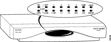
The Cisco uBR925 cable access router contains 15 LEDs on the front panel that provide information about the router's status and network connections. Figure 1-5 illustrates the LEDs on the router's front panel, and Table 1-1 lists the meaning for each LED.
Figure 1-5 Cisco uBR925 Cable Access Router Front Panel LEDs
| Label | Description | Color | Function |
|---|---|---|---|
| OK | System Status | Green | On = Cisco uBR925 cable access router power on and self-test diagnostics have finished successfully, the system image has been booted, and the system is operational. Blink = After power on and self-test diagnostics have finished successfully, LED blinks as the Cisco IOS software image is booted. Off = No Power. If the OK LED turns off and remains off during the boot process, the router has failed its self-test diagnostics. In this situation the bottom row of LEDs contain more information about the type of failure (see Table 4-1). |
| ACT | Cable Activity | Green | Blink = Activity on the cable RF interface. |
| USB | USB Activity | Green | On = USB cable connected, the interface is enabled, and the link is up. |
| 1-4 | Ethernet 1, Ethernet 2, Ethernet 3, Ethernet 4 | Green | On = Ethernet cable is connected, the interface is enabled, and the link is up. |
| LINK | Cable RF Link | Green | On = Cable is connected and the RF link is up. |
| V OK | Voice System Status | Green | On = VoIP system is enabled and operational. |
| V1 | Voice Port 1 | Green | On = Call in progress on voice port 1. |
| V2 | Voice Port 2 | Green | On = Call in progress on voice port 2. |
| DS | Downstream Signal Lock Status | Green | On = Cisco uBR925 cable access router is locked to a downstream frequency (channel). |
| US | Upstream Signal Quality | Green | On = Cisco uBR925 cable access router has established upstream communications with the CMTS; cable access router has completed the DOCSIS ranging state 2, has entered provisioning state, and is communicating within 6 dB of the desired final power level (generally within 3 dB). Off = Cisco uBR925 cable access router has not completed secondary ranging; the CMTS has heard from the cable access router, however, and there is some upstream continuity. |
| DSNR | Downstream Signal-to-Noise Ratio | Green | On = Receiving quality, downstream signal; SNR is greater than 5 dB above the downstream lock threshold. Off = Receiving low or marginal downstream signal strength or quality. Note |
| MSG | Message Waiting | Green | No default function defined. The service provider can use SNMP set requests to use this LED for custom applications or services. |
| UPS | — | — | Reserved for future use. |
Data Ports
As shown in Figure 1-4, the Cisco uBR925 cable access router contains the following data connectors:
•![]() Coaxial cable F-connector —Provides the connection to the CMTS and cable network. The coaxial cable connector is a single cable interface (Cable 0) and must always be connected to the cable system for proper operation.
Coaxial cable F-connector —Provides the connection to the CMTS and cable network. The coaxial cable connector is a single cable interface (Cable 0) and must always be connected to the cable system for proper operation.
•![]() Four Ethernet 10Base T hub ports—Provides connectivity to the subscriber CPE devices. The Ethernet ports are in a hub configuration that forms one logical Ethernet interface (Ethernet 0). When the Cisco uBR925 cable access router transmits data to the Ethernet interface, it is broadcast out all four ports.
Four Ethernet 10Base T hub ports—Provides connectivity to the subscriber CPE devices. The Ethernet ports are in a hub configuration that forms one logical Ethernet interface (Ethernet 0). When the Cisco uBR925 cable access router transmits data to the Ethernet interface, it is broadcast out all four ports.
PCs and other CPE devices can be connected to the Ethernet ports using one of the following configurations:
–![]() If the router is configured for bridging mode, from one to four CPE devices can be connected directly to the router.
If the router is configured for bridging mode, from one to four CPE devices can be connected directly to the router.
–![]() If the router is configured for bridging mode, an Ethernet hub can be connected to one of the router's Ethernet ports. The hub can then be connected to up to 254 additional CPE devices.
If the router is configured for bridging mode, an Ethernet hub can be connected to one of the router's Ethernet ports. The hub can then be connected to up to 254 additional CPE devices.
–![]() If the router is configured for routing mode, up to four CPE devices can be directly connected to the router's Ethernet ports.
If the router is configured for routing mode, up to four CPE devices can be directly connected to the router's Ethernet ports.
–![]() If the router is configured for routing mode, an Ethernet hub can be connected to one of the router's Ethernet ports. The hub can then be connected to any number of devices.
If the router is configured for routing mode, an Ethernet hub can be connected to one of the router's Ethernet ports. The hub can then be connected to any number of devices.
Note ![]() For network performance reasons, Cisco recommends a maximum of 16 CPE devices in either bridging or routing mode. The service provider may also set a different limit by changing the MAX CPE parameter in the DOCSIS configuration file—the default MAX CPE value is one CPE device, which applies in both bridging and routing modes.
For network performance reasons, Cisco recommends a maximum of 16 CPE devices in either bridging or routing mode. The service provider may also set a different limit by changing the MAX CPE parameter in the DOCSIS configuration file—the default MAX CPE value is one CPE device, which applies in both bridging and routing modes.
•![]() USB device (type "B") port—Provides network connectivity to one PC running the Windows 98, Windows 98 Second Edition, Windows 2000, or Windows Millennium operating system.
USB device (type "B") port—Provides network connectivity to one PC running the Windows 98, Windows 98 Second Edition, Windows 2000, or Windows Millennium operating system.
•![]() Console port connector—Provides access to the router's command-line interface (CLI). See the Cisco uBR905/uBR925 Cable Access Router Software Configuration Guide for more details on using this port and giving CLI commands.
Console port connector—Provides access to the router's command-line interface (CLI). See the Cisco uBR905/uBR925 Cable Access Router Software Configuration Guide for more details on using this port and giving CLI commands.
Note ![]() The Cisco uBR925 cable access router ships from the Cisco factory with the console port enabled. By default, downloading a Cisco IOS configuration file disables the console port and erases all previously saved configurations. This default behavior prohibits configuration access at the remote site.
The Cisco uBR925 cable access router ships from the Cisco factory with the console port enabled. By default, downloading a Cisco IOS configuration file disables the console port and erases all previously saved configurations. This default behavior prohibits configuration access at the remote site.
Voice Ports
The Cisco uBR925 cable access router contains two analog (FXS) voice ports at the rear of the unit. These ports can be connected directly to analog telephones, modems, or fax devices in the following ways:
•![]() A single-line telephone, modem, or fax device can be connected to each voice port, using a two-wire connection.
A single-line telephone, modem, or fax device can be connected to each voice port, using a two-wire connection.
•![]() A two-line analog telephone, modem, or fax device can be connected to the voice port labeled V1+V2, using a four-wire connection. When a two-line telephone is plugged into these ports, the second line acts as if it were plugged into the V2 port. If two-line telephones are used, devices plugged into the V2 port act as extensions to the second line of the two-line telephones.
A two-line analog telephone, modem, or fax device can be connected to the voice port labeled V1+V2, using a four-wire connection. When a two-line telephone is plugged into these ports, the second line acts as if it were plugged into the V2 port. If two-line telephones are used, devices plugged into the V2 port act as extensions to the second line of the two-line telephones.
•![]() Adapters can be used to connect multiple analog devices to a single voice port. When multiple telephones are connected to a voice port, they function as extensions.
Adapters can be used to connect multiple analog devices to a single voice port. When multiple telephones are connected to a voice port, they function as extensions.
The Cisco uBR925 cable access router supports up to two simultaneous voice connections, one on each voice port. Only one voice call—telephone, modem, or fax —per VoIP line is active at a time. The actual number of voice ports and voice devices supported depends on the Cisco IOS image being used and the services purchased from the service provider.
Caution ![]() Do not connect the voice ports to telephone wires that exit the building under any circumstances—this is a safety hazard. The Cisco uBR925 cable access router is not designed to connect to the Public Telephone Switched Network (PTSN).
Do not connect the voice ports to telephone wires that exit the building under any circumstances—this is a safety hazard. The Cisco uBR925 cable access router is not designed to connect to the Public Telephone Switched Network (PTSN).
Multiple analog telephone devices can be connected to each of the VoIP telephone lines, provided the total Ringer Equivalence Number (REN) for all telephones does not exceed the limits given in "Technical Specifications."
A REN value is assigned to each terminal device to denote the percentage of the total load to be connected to the telephone loop used by the device, to prevent overloading. When the REN value is exceeded, the telephones might not ring properly or at all.
Power Supply
The Cisco uBR925 cable access router uses an external AC-input power supply. Refer to Table A-1 in "Technical Specifications," for the AC-input power supply power specifications, including input voltage and operating frequency ranges.
The Cisco uBR925 cable access router does not contain a power switch. After the cable system technician installs, connects, powers on, and initializes the unit, it is intended to remain connected to the broadband network when operating normally.
The same power supply supports both domestic (U.S.) and international operation. Different power cords are required, however, depending on the country of operation.

Warning ![]() Read the installation instructions before you connect the system to its power source. (To see translations of the warnings that appear in this publication, refer to the appendix "Translated Safety Warnings.")
Read the installation instructions before you connect the system to its power source. (To see translations of the warnings that appear in this publication, refer to the appendix "Translated Safety Warnings.")
Warning ![]() The router is designed to work with TN power systems. (To see translations of the warnings that appear in this publication, refer to the appendix "Translated Safety Warnings.")
The router is designed to work with TN power systems. (To see translations of the warnings that appear in this publication, refer to the appendix "Translated Safety Warnings.")
Warning ![]() Never defeat the ground conductor or operate the equipment in the absence of a suitably installed ground conductor. Contact the appropriate electrical inspection authority or an electrician if you are uncertain that suitable grounding is available. (To see translations of the warnings that appear in this publication, refer to the appendix "Translated Safety Warnings.")
Never defeat the ground conductor or operate the equipment in the absence of a suitably installed ground conductor. Contact the appropriate electrical inspection authority or an electrician if you are uncertain that suitable grounding is available. (To see translations of the warnings that appear in this publication, refer to the appendix "Translated Safety Warnings.")
Caution ![]() Use only the power supply provided by Cisco and a power cord appropriate to the country of operation. Using any other vendor's power supply can cause loss of data or permanent damage.
Use only the power supply provided by Cisco and a power cord appropriate to the country of operation. Using any other vendor's power supply can cause loss of data or permanent damage.
Functional Overview
This section provides a functional overview of the operation of the Cisco uBR925 cable access router, and is divided into the following categories:
•![]() Initial Power On and Provisioning
Initial Power On and Provisioning
•![]() Data Operations
Data Operations
•![]() Voice Operations
Voice Operations
Initial Power On and Provisioning
The Cisco uBR925 cable access router ships from the Cisco factory ready to work in a DOCSIS-compliant bridging mode. However, before the router can transmit traffic, the CMTS at the headend must properly provision the router as follows:
1. ![]() The appropriate service must be purchased from the cable system. If certain features, such as IPsec data encryption, are desired, a license for the appropriate Cisco IOS software image must also be purchased.
The appropriate service must be purchased from the cable system. If certain features, such as IPsec data encryption, are desired, a license for the appropriate Cisco IOS software image must also be purchased.
2. ![]() When the router is first brought online, the CMTS at the headend downloads a DOCSIS configuration file to the router. This file—which is a binary file that must be in the format required by the DOCSIS specification—configures the router for the appropriate level of services and sets other parameters as needed.
When the router is first brought online, the CMTS at the headend downloads a DOCSIS configuration file to the router. This file—which is a binary file that must be in the format required by the DOCSIS specification—configures the router for the appropriate level of services and sets other parameters as needed.
3. ![]() At this point, the router is completely configured for basic DOCSIS operations, but if additional features beyond those in the default Cisco IOS software image are desired, the DOCSIS configuration file can also specify that the router should download another Cisco IOS image from the CMTS.
At this point, the router is completely configured for basic DOCSIS operations, but if additional features beyond those in the default Cisco IOS software image are desired, the DOCSIS configuration file can also specify that the router should download another Cisco IOS image from the CMTS.
4. ![]() To configure the Cisco uBR925 cable access router for any additional features, the cable service provider can do any or all of the following:
To configure the Cisco uBR925 cable access router for any additional features, the cable service provider can do any or all of the following:
–![]() Cisco IOS commands can be included in the Vendor Specific Information field (suboption 131) in the DOCSIS configuration file.
Cisco IOS commands can be included in the Vendor Specific Information field (suboption 131) in the DOCSIS configuration file.
–![]() The Cisco uBR925 cable access router can download a Cisco IOS configuration file from a TFTP server that is specified by the DOCSIS configuration file. The Cisco IOS configuration file is an ASCII text file that contains the Cisco IOS commands needed to configure the router for any additional features.
The Cisco uBR925 cable access router can download a Cisco IOS configuration file from a TFTP server that is specified by the DOCSIS configuration file. The Cisco IOS configuration file is an ASCII text file that contains the Cisco IOS commands needed to configure the router for any additional features.
–![]() A system administrator can manually configure the Cisco uBR925 cable access router by giving Cisco IOS commands at the CLI interface. This can be done either locally by connecting to the system's RJ-45 console port, or remotely by establishing a Telnet connection with the unit.
A system administrator can manually configure the Cisco uBR925 cable access router by giving Cisco IOS commands at the CLI interface. This can be done either locally by connecting to the system's RJ-45 console port, or remotely by establishing a Telnet connection with the unit.
–![]() If SNMP management has been enabled, certain parameters can be queried and configured using an SNMP manager at the cable provider's network operations center (NOC).
If SNMP management has been enabled, certain parameters can be queried and configured using an SNMP manager at the cable provider's network operations center (NOC).
Note ![]() The CMTS Cisco uBR925 cable access router downloads the DOCSIS configuration file (and a Cisco IOS configuration file, if specified) each time it is powered on, but it downloads the Cisco IOS image (if specified) only once when the router is initially brought online. However, a new configuration file or image can be downloaded whenever necessary, such as when the cable service offers new services or subscribers upgrade their services.
The CMTS Cisco uBR925 cable access router downloads the DOCSIS configuration file (and a Cisco IOS configuration file, if specified) each time it is powered on, but it downloads the Cisco IOS image (if specified) only once when the router is initially brought online. However, a new configuration file or image can be downloaded whenever necessary, such as when the cable service offers new services or subscribers upgrade their services.
To ensure that subscribers obtain the exact services that they have ordered, the Cisco uBR925 cable access router arrives from the Cisco factory with a unique identifier (UID) that consists of a serial number and MAC address. These factory-assigned values are on a label at the bottom of the router. For convenience, these values are also in a barcode label that can be easily scanned for easy entry into the service provider's provisioning and billing system.
Using the MAC address of the router as the key, the CMTS downloads the DOCSIS configuration file and Cisco IOS image that will provide the services that this particular subscriber has purchased. Service technicians at the headend typically create a number of standard configuration files to match the range of services offered by the provider. These configuration files can be created manually or with tools provided by Cisco Systems for this purpose.
The following sections describe the initial power on and provisioning sequence in more detail, as well as the requirements that must be met by both the router and the CMTS before provisioning can succeed.
Initial Power On Sequence
When connected and first powered on, the Cisco uBR925 cable access router performs the following DOCSIS-mandated procedure for automatic installation and configuration:
1. ![]() The router boots the read-only memory (ROM) from the ROMMON partition of its Flash memory.
The router boots the read-only memory (ROM) from the ROMMON partition of its Flash memory.
2. ![]() The router performs a self-test, initializes processor hardware, and boots the main operating system software—the Cisco IOS release image stored in Flash memory.
The router performs a self-test, initializes processor hardware, and boots the main operating system software—the Cisco IOS release image stored in Flash memory.
3. ![]() The router acquires a temporary downstream channel by matching the clock sync signal that is regularly sent out by the CMTS on the downstream channel.
The router acquires a temporary downstream channel by matching the clock sync signal that is regularly sent out by the CMTS on the downstream channel.
4. ![]() The router then waits for an Upstream Channel Descriptor (UCD) message from the CMTS and configures itself for the upstream frequency specified in that message.
The router then waits for an Upstream Channel Descriptor (UCD) message from the CMTS and configures itself for the upstream frequency specified in that message.
5. ![]() The router waits for the next upstream bandwidth allocation map message (MAP). These messages are regularly sent from the CMTS to find the next available shared request time slot. The router then uses this time slot to send a ranging request message to the CMTS, communicating the router's user ID (UID, which includes its unique MAC address), using a temporary service identifier (SID) of 0 (zero) to indicate that it has not yet been allocated to an upstream channel.
The router waits for the next upstream bandwidth allocation map message (MAP). These messages are regularly sent from the CMTS to find the next available shared request time slot. The router then uses this time slot to send a ranging request message to the CMTS, communicating the router's user ID (UID, which includes its unique MAC address), using a temporary service identifier (SID) of 0 (zero) to indicate that it has not yet been allocated to an upstream channel.
6. ![]() In reply to the router's ranging request, the CMTS sends a ranging response containing a temporary SID to be used for the initial router configuration and bandwidth allocation. As needed, the router adjusts its transmit power levels by using the power increment value given by the CMTS in its ranging response message.
In reply to the router's ranging request, the CMTS sends a ranging response containing a temporary SID to be used for the initial router configuration and bandwidth allocation. As needed, the router adjusts its transmit power levels by using the power increment value given by the CMTS in its ranging response message.
Note ![]() At this point, the router has established connectivity with the CMTS but is not yet online. The next steps allocate permanent upstream and downstream frequencies, and the configuration required for IP network connectivity.
At this point, the router has established connectivity with the CMTS but is not yet online. The next steps allocate permanent upstream and downstream frequencies, and the configuration required for IP network connectivity.
7. ![]() After the next MAP message broadcast, the router uses a shared request time slot to invoke the Dynamic Host Configuration Protocol (DHCP) to establish IP connectivity with the TCP/IP network at the headend.
After the next MAP message broadcast, the router uses a shared request time slot to invoke the Dynamic Host Configuration Protocol (DHCP) to establish IP connectivity with the TCP/IP network at the headend.
8. ![]() The DHCP server—typically a dedicated server at the headend, but it could also be a CMTS such as a Cisco uBR7200 series universal broadband router—sends a response containing the router's IP address, as well as the IP addresses for the default gateway and time of day (ToD) server. The DHCP server also sends the IP address for the authorized Trivial File Transfer Protocol (TFTP) server from which the router should download its DOCSIS configuration file. Depending on the particular network configuration, other information could be provided, such as the IP addresses for a syslog server or security server.
The DHCP server—typically a dedicated server at the headend, but it could also be a CMTS such as a Cisco uBR7200 series universal broadband router—sends a response containing the router's IP address, as well as the IP addresses for the default gateway and time of day (ToD) server. The DHCP server also sends the IP address for the authorized Trivial File Transfer Protocol (TFTP) server from which the router should download its DOCSIS configuration file. Depending on the particular network configuration, other information could be provided, such as the IP addresses for a syslog server or security server.
9. ![]() The router configures itself for the specified IP address and gets the current date and time from the specified ToD server.
The router configures itself for the specified IP address and gets the current date and time from the specified ToD server.
10. ![]() Using the TFTP protocol, the router downloads the specified DOCSIS configuration file and configures itself for the appropriate parameters. The DOCSIS configuration file defines the router's operating mode such as:
Using the TFTP protocol, the router downloads the specified DOCSIS configuration file and configures itself for the appropriate parameters. The DOCSIS configuration file defines the router's operating mode such as:
–![]() the provisioned downstream and upstream service assignments
the provisioned downstream and upstream service assignments
–![]() assigned frequencies, data rates
assigned frequencies, data rates
–![]() modulation schemes
modulation schemes
–![]() Class of Service (CoS)
Class of Service (CoS)
–![]() type of services to support
type of services to support
Cisco provides tools to help automate the creation of configuration files.
Caution ![]() The DOCSIS configuration file must be in the exact format given by the DOCSIS specification. An incorrect DOCSIS configuration file can cause the Cisco uBR925 cable access router to constantly cycle offline. Such errors include wrong downstream frequency, wrong UCD, wrong downstream Channel ID, invalid CoS, incorrect BPI privacy configurations, or shared secret strings.
The DOCSIS configuration file must be in the exact format given by the DOCSIS specification. An incorrect DOCSIS configuration file can cause the Cisco uBR925 cable access router to constantly cycle offline. Such errors include wrong downstream frequency, wrong UCD, wrong downstream Channel ID, invalid CoS, incorrect BPI privacy configurations, or shared secret strings.
11. ![]() The router sends another registration request to the CMTS containing the CoS parameters given in the DOCSIS configuration file.
The router sends another registration request to the CMTS containing the CoS parameters given in the DOCSIS configuration file.
12. ![]() The CMTS verifies that the router is using the appropriate CoS profile and converts the temporary SID into a data SID with a service class index that points to the applicable CoS profile.
The CMTS verifies that the router is using the appropriate CoS profile and converts the temporary SID into a data SID with a service class index that points to the applicable CoS profile.
Note ![]() Depending on the software image being run and the capabilities of the CMTS, the DOCSIS configuration file can also specify multiple CoS profiles. Each CoS profile is assigned its own SID, either dynamically or statically, depending on the capabilities of the CMTS and software image being used.
Depending on the software image being run and the capabilities of the CMTS, the DOCSIS configuration file can also specify multiple CoS profiles. Each CoS profile is assigned its own SID, either dynamically or statically, depending on the capabilities of the CMTS and software image being used.
13. ![]() The router completes its secondary ranging and is then online, passing data between the cable network and the PCs and other customer premises equipment that is connected to the router.
The router completes its secondary ranging and is then online, passing data between the cable network and the PCs and other customer premises equipment that is connected to the router.
Note ![]() At this point the router is online and operational in the basic DOCSIS bridging mode ("plug and play" mode). The next step is done only if the DOCSIS configuration file specifies that the router must also download a Cisco IOS configuration file and new Cisco IOS image.
At this point the router is online and operational in the basic DOCSIS bridging mode ("plug and play" mode). The next step is done only if the DOCSIS configuration file specifies that the router must also download a Cisco IOS configuration file and new Cisco IOS image.
14. ![]() If the DOCSIS configuration file specifies that the router must download a secondary Cisco IOS image and a Cisco IOS configuration file, the router uses TFTP to download the image and configuration files into its local memory. The router then installs the new Cisco IOS image and runs the configuration file.
If the DOCSIS configuration file specifies that the router must download a secondary Cisco IOS image and a Cisco IOS configuration file, the router uses TFTP to download the image and configuration files into its local memory. The router then installs the new Cisco IOS image and runs the configuration file.
Alternatively, a system administrator can manually configure the Cisco uBR925 cable access router by giving commands at the router's CLI interface or by using an SNMP manager.
15. ![]() If Baseline Privacy Interface (BPI) encryption is configured and enabled on both the router and CMTS, the router and CMTS negotiate the appropriate encryption parameters. After encryption is enabled, all information within Ethernet packets that is sent between the router and CMTS is encrypted to prevent interception or modification by an unauthorized party.
If Baseline Privacy Interface (BPI) encryption is configured and enabled on both the router and CMTS, the router and CMTS negotiate the appropriate encryption parameters. After encryption is enabled, all information within Ethernet packets that is sent between the router and CMTS is encrypted to prevent interception or modification by an unauthorized party.
Figure 1-6 illustrates the traffic flow during this process.
Figure 1-6 Cisco uBR925 Cable Access Router Provisioning Overview
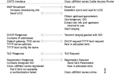
Note ![]() For more detail on the provisioning process, see the DOCSIS 1.0 Radio Frequency Interface (RFI) specification (SP-RFII01-990731 or later revision).
For more detail on the provisioning process, see the DOCSIS 1.0 Radio Frequency Interface (RFI) specification (SP-RFII01-990731 or later revision).
After the Cisco uBR925 cable access router goes online, it sends data traffic between the attached CPE devices and the network. The service provider typically uses DHCP to assign IP addresses to the CPE devices. The number of IP addresses each subscriber can obtain depends on the services purchased from the provider.
Provisioning Prerequisites
The following requirements must be met before a router can be provisioned:
•![]() All required CMTS routing and network interface equipment must be installed, configured, and operational. This includes all headend routers, servers (DHCP, TFTP, and ToD), network management systems, and other configuration or billing systems required for your network.
All required CMTS routing and network interface equipment must be installed, configured, and operational. This includes all headend routers, servers (DHCP, TFTP, and ToD), network management systems, and other configuration or billing systems required for your network.
•![]() Based on the quality and capacity of your cable plant, your system administrator or network planner must have defined your network's IP address allocation plan; the spectrum management plan outlining the recommended operating parameters to optimize performance; and the channel plan identifying the channels available to assign to specific Cisco uBR925 cable access routers.
Based on the quality and capacity of your cable plant, your system administrator or network planner must have defined your network's IP address allocation plan; the spectrum management plan outlining the recommended operating parameters to optimize performance; and the channel plan identifying the channels available to assign to specific Cisco uBR925 cable access routers.
•![]() A CMTS customer service representative must have recorded all needed subscriber information, initiated a work order, and arranged an installation date with the subscriber.
A CMTS customer service representative must have recorded all needed subscriber information, initiated a work order, and arranged an installation date with the subscriber.
•![]() The CMTS system administrator or appropriate personnel must have specified the policy parameters for the Cisco uBR925 cable access router and all computers and other CPE devices to be supported at the subscriber site. See Cisco's Network Registrar (CNR) product documentation for more information.
The CMTS system administrator or appropriate personnel must have specified the policy parameters for the Cisco uBR925 cable access router and all computers and other CPE devices to be supported at the subscriber site. See Cisco's Network Registrar (CNR) product documentation for more information.
•![]() The CMTS system administrator or appropriate personnel must have defined and pushed DHCP and DOCSIS configuration files to the appropriate servers so that each router, when initialized, can transmit a DHCP request, receive its IP address, obtain its TFTP and ToD server addresses, and download its DOCSIS configuration file. Cisco IOS images and Cisco IOS configuration files must also be prepared for subscribers who are purchasing services that require new software images and advanced configurations.
The CMTS system administrator or appropriate personnel must have defined and pushed DHCP and DOCSIS configuration files to the appropriate servers so that each router, when initialized, can transmit a DHCP request, receive its IP address, obtain its TFTP and ToD server addresses, and download its DOCSIS configuration file. Cisco IOS images and Cisco IOS configuration files must also be prepared for subscribers who are purchasing services that require new software images and advanced configurations.
Note ![]() The CMTS uses the router's unique MAC address for the cable interface to ensure that the router downloads only the files appropriate for the levels of service that have been purchased.
The CMTS uses the router's unique MAC address for the cable interface to ensure that the router downloads only the files appropriate for the levels of service that have been purchased.
•![]() If DHCP is also being used to provision the IP addresses used by the CPE devices at the subscriber's site, the DHCP server must be able to respond to those requests.
If DHCP is also being used to provision the IP addresses used by the CPE devices at the subscriber's site, the DHCP server must be able to respond to those requests.
•![]() The CMTS system administrator must ensure that appropriate databases are updated to activate and support the new subscriber account in the provisioning, billing, and network management systems in place for your network after each router is registered with the CMTS.
The CMTS system administrator must ensure that appropriate databases are updated to activate and support the new subscriber account in the provisioning, billing, and network management systems in place for your network after each router is registered with the CMTS.
•![]() The following files should be prepared and available on the TFTP server:
The following files should be prepared and available on the TFTP server:
–![]() DOCSIS configuration file—This is required for every installation. The DOCSIS configuration file specifies the DOCSIS-mandated parameters, such as upstream and downstream frequencies, and optional features, such as whether to download a new software image or a Cisco IOS configuration file.
DOCSIS configuration file—This is required for every installation. The DOCSIS configuration file specifies the DOCSIS-mandated parameters, such as upstream and downstream frequencies, and optional features, such as whether to download a new software image or a Cisco IOS configuration file.
–![]() Cisco IOS image—If upgrading to a Cisco IOS image different from the factory default, the new image must be specified in the router's DOCSIS configuration file and be available on a TFTP server that is accessible through the cable interface.
Cisco IOS image—If upgrading to a Cisco IOS image different from the factory default, the new image must be specified in the router's DOCSIS configuration file and be available on a TFTP server that is accessible through the cable interface.
–![]() Cisco IOS configuration file—Unless the network administrator at the subscriber's site is manually configuring the Cisco uBR925 cable access router through its command-line interface, a Cisco IOS configuration file must be prepared that specifies the routing parameters required to route data between the cable and serial interfaces. This file can specify any other optional features that are desired and must be made available on a TFTP server that is accessible through the cable interface.
Cisco IOS configuration file—Unless the network administrator at the subscriber's site is manually configuring the Cisco uBR925 cable access router through its command-line interface, a Cisco IOS configuration file must be prepared that specifies the routing parameters required to route data between the cable and serial interfaces. This file can specify any other optional features that are desired and must be made available on a TFTP server that is accessible through the cable interface.
Upgrading the Software Image
When Cisco IOS images are updated to new releases, the service provider can download them as needed to Cisco uBR925 cable access routers installed in the field (based on the software licenses purchased). See the release notes for the router for a complete list of features and Cisco IOS images that are currently supported.
Service providers can use the router's Media Access Controller (MAC) address to uniquely identify each particular router in the field. The CMTS uses this value to download the proper DOCSIS configuration file to the router before it begins operation.
The DOCSIS configuration file can also contain the name of the software image that the router should be running. If necessary, the CMTS can download the proper software image to the router and force it to reboot using the new image.
The download of the DOCSIS configuration file usually takes only a few seconds and is done every time the Cisco uBR925 cable access router reboots. The download of the software image can take several minutes to complete, during which time network connectivity is not available. However, the software image must be downloaded only once, until the subscriber needs to be updated with a new or updated image.
See the Cisco uBR905/uBR925 Cable Access Router Software Configuration Guide for a description on how to download a software image and configuration file to a Cisco uBR925 cable access router installed in the field.
Data Operations
This section provides an overview of how data is transmitted to and from the Cisco uBR925 cable access router across the cable system's HFC network. Figure 1-7 illustrates a typical broadband data cable system, which shows the network path between the Cisco uBR925 cable access router and the CMTS headend equipment (Cisco uBR7200 series universal broadband router or other DOCSIS-compliant CMTS).
Figure 1-7 Cisco Broadband Data Cable System
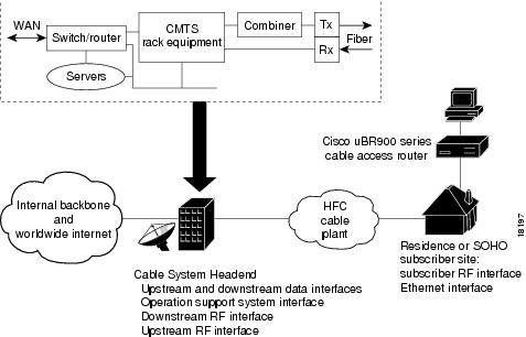
The Cisco uBR925 cable access router provides the connection between the PC and the cable system, modulating the data transmitted to and from the PC so that the data can be efficiently carried over the coaxial cable installed by the service provider. To avoid interfering with the cable video signals that are also transmitted over this same coaxial cable, the DOCSIS specification allows only certain frequencies to be used for data transmissions. Separate frequencies are used for the data sent from the CMTS to the cable modem (the downstream direction), and for the data sent from the cable modem to the CMTS (the upstream direction).
The CMTS divides the cable plant into downstream channels, and upstream segments or clusters of nodes. Each Cisco uBR925 cable access router on the network is configured to receive data on a particular downstream channel. A downstream channel contains one or more upstream segments; partitioning the upstream plant into smaller segments significantly reduces the number of potential ingress sources and failure points.
Downstream Transmissions
Because 90 percent of the data transmitted on the Internet is, on average, sent from the network to the user, the cable system allocates the majority of bandwidth for downstream data (data sent from the CMTS to the router). Downstream transmissions use a 6-MHz data channel in the 88 to 860 MHz range, providing an approximate maximum bandwidth of 27 or 26 Mbps. This bandwidth is shared among all subscribers who have been assigned to this particular downstream channel.
The CMTS receives the downstream data from its Internet or other WAN connections, addresses the data to the appropriate Cisco uBR925 cable access router, and modulates it for transmission on the cable network. When the data arrives at the subscriber's site, the router modulates it for transmission over the Ethernet connection to the appropriate CPE device.
Upstream Transmissions
The data transmitted in the upstream direction (from the user to the network) is typically much less than that on the downstream direction, therefore a smaller bandwidth is allocated to it. The upstream transmissions share a 200 kHz-wide to 3.2 MHz-wide channel in the 5 to 42 MHz range, providing a bandwidth of up to 10 Mbps.
Typically, service providers allocate different upstream bandwidths depending on the services purchased by a subscriber. For example, a business purchasing basic service might be allocated a 128 kbps upstream, but businesses purchasing premium services might be allocated a 384 kbps upstream. The CMTS enforces this maximum bandwidth on a per cable modem basis, so that each user receives the services purchased.
The CMTS allocates an upstream frequency to the Cisco uBR925 cable access router when it first registers on the system. The CMTS can then move the router to a new upstream or a new upstream frequency as needed to respond to current network conditions and noise levels.
Depending on the bandwidths allocated to each user, the quality of the physical plant, and the CMTS used at the headend, users on a single downstream can be allocated across several upstreams. This ensures a responsive network for all users and simplifies bandwidth management when new users are added, or when a user wants to upgrade to a higher bandwidth service.
The Cisco uBR925 cable access router receives the upstream data from the CPE devices to which it is connected. The router modulates this data for transmission on the coaxial cable system to the CMTS. The CMTS then routes the data to the appropriate destination (local server, Internet, and so forth) through its WAN interfaces.
The Cisco uBR925 cable access router uses a request/grant mechanism to obtain upstream bandwidth, where each user on the upstream must make a specific request before being allowed to transmit on the upstream. DOCSIS rules and the maximum bandwidth cap prevent any single user from monopolizing the upstream bandwidth. If supported by the CMTS, the Cisco uBR925 cable access router supports DOCSIS 1.1 concatenation, whereby multiple transmissions can be combined into one bandwidth request, reducing overhead and maximizing bandwidth efficiency.
The Cisco uBR925 cable access router also supports unsolicited grants, in which part of the upstream bandwidth is reserved for a particular use. This allows service providers to sell services with both a maximum bandwidth and a guaranteed bandwidth. (The CMTS must also support this feature and be configured on a per-user basis.)
Note ![]() End-to-end throughput varies based on the design and loading of network components, the mix of traffic, the processing speed and interface of the host servers, the processing speed and local Ethernet performance of the subscriber's computer, as well as other parameters. Because the network can be configured to support multiple levels of service with different performance requirements, the subscriber's service level agreement also affects throughput. DOCSIS also specifies fundamental performance limitations to ensure that the majority of subscribers experience good performance, rather than permitting a few users to consume the entire capacity.
End-to-end throughput varies based on the design and loading of network components, the mix of traffic, the processing speed and interface of the host servers, the processing speed and local Ethernet performance of the subscriber's computer, as well as other parameters. Because the network can be configured to support multiple levels of service with different performance requirements, the subscriber's service level agreement also affects throughput. DOCSIS also specifies fundamental performance limitations to ensure that the majority of subscribers experience good performance, rather than permitting a few users to consume the entire capacity.
Security
The Cisco uBR925 cable access router provides the following basic options to protect the data it transmits over public networks:
•![]() Baseline Privacy Interface (BPI)—Encrypts the Ethernet packets transmitted over the cable interface between a cable modem and CMTS.
Baseline Privacy Interface (BPI)—Encrypts the Ethernet packets transmitted over the cable interface between a cable modem and CMTS.
•![]() IPsec network security—Provides robust authentication and end-to-end encryption of IP packets over an unprotected network such as the Internet.
IPsec network security—Provides robust authentication and end-to-end encryption of IP packets over an unprotected network such as the Internet.
Baseline Privacy Interface
BPI security is defined by the DOCSIS 1.0 BPI specification (SP-BPI-I02-990319 or later revision). Both the CMTS and Cisco uBR925 cable access router must support BPI security and enable its use before this option can be used.
When using BPI security, the CMTS and Cisco uBR925 cable access router encrypt all data before transmitting it on the cable interface. Data is encrypted using a 40-bit or 56-bit data encryption algorithm, which prevents unauthorized parties from intercepting and reading the data as it travels across the cable network.
When using the BPI option, the Cisco uBR925 cable access router uses a uniquely assigned key encryption key (kek) to connect to the CMTS. The kek authorizes the router to negotiate a traffic encryption key (tek), which the router and CMTS use to encrypt and decrypt the data sent on the cable interface. The keys have a limited lifespan, and the router must request a new key before the current one expires.
IPsec Network Security
IPsec is a framework of open standards developed by the Internet Engineering Task Force (IETF) for the secure transmission of sensitive information over unprotected networks such as the Internet. IPsec acts at the network layer (Layer 3), protecting and authenticating IP packets between participating IPsec devices ("peers") such as the Cisco uBR925 cable access router.
IPsec encryption provides end-to-end protection across public and insecure networks such as the Internet. Two levels of encryption—56-bit and 168-bit—are available, depending on the software image being used. Keys can be pre-shared or determined from a digital certificate that has been verified by a certificate authority.
The Cisco uBR925 cable access router provides a hardware IPsec accelerator with greatly improved performance over software-based IPsec encryption. Subscribers can have the protection of IPsec encryption without sacrificing the high-speed performance of a cable network.
Note ![]() Cisco IOS images with strong encryption (including, but not limited to, 168-bit [3DES] data encryption feature sets) are subject to United States government export controls and have limited distribution. Strong encryption images to be installed outside the United States may require an export license. Customer orders may be denied or subject to delay due to United States government regulations. When applicable, the purchaser or user must obtain local import and use authorizations for all encryption strengths. Contact your sales representative or distributor for more information, or send an e-mail to export@cisco.com.
Cisco IOS images with strong encryption (including, but not limited to, 168-bit [3DES] data encryption feature sets) are subject to United States government export controls and have limited distribution. Strong encryption images to be installed outside the United States may require an export license. Customer orders may be denied or subject to delay due to United States government regulations. When applicable, the purchaser or user must obtain local import and use authorizations for all encryption strengths. Contact your sales representative or distributor for more information, or send an e-mail to export@cisco.com.
Voice Operations
The Cisco uBR925 cable access router supports Voice over IP (VoIP), which transmits voice, modem, and fax calls over a TCP/IP network such as the Internet. Depending on the services purchased from the cable service provider, subscribers can place and receive calls without using the local exchange carrier.
The cable access router contains two voice ports, which support two simultaneous voice, modem, and fax calls. You can connect a single-line telephone or fax device to each voice port, or you can connect a dual-line telephone or fax device to the first voice port.
Subscribers can connect standard analog telephones, modems, and fax machines to the Cisco uBR925 cable access router; IP telephones are not required. Depending on the voice network set up by the service provider, subscribers can place calls to numbers that are in the existing telco network; the called party does not have to be using VoIP telephone service.
Note ![]() The Cisco uBR925 cable access router provides FXS (Foreign Exchange Station) services and supports analog phones, faxes, and modems. The Cisco uBR925 cable access router's voice ports do not support devices requiring Foreign Exchange Office (FXO) services, such as PBX devices.
The Cisco uBR925 cable access router provides FXS (Foreign Exchange Station) services and supports analog phones, faxes, and modems. The Cisco uBR925 cable access router's voice ports do not support devices requiring Foreign Exchange Office (FXO) services, such as PBX devices.
You can also connect multiple telephones, modems, and fax devices to a single voice line. However, each multiple device acts as an extension to that voice line, so only one call at a time can be made per voice line. The Cisco uBR925 cable access router supports multiple devices per voice line, however, the total REN value for all devices must not exceed the maximum number given in "Technical Specifications."
Note ![]() The REN value is a measure of the AC load that the device places on a voice line and is typically listed on each device. If too many devices are connected to the line, the telephones might not ring properly, and you might have difficultly completing telephone calls.
The REN value is a measure of the AC load that the device places on a voice line and is typically listed on each device. If too many devices are connected to the line, the telephones might not ring properly, and you might have difficultly completing telephone calls.
Telephones at each subscriber site must support touch-tone dialing; rotary dialing is not supported. Special telephone features such as call waiting, forwarding, and conferencing are supported only if using a Cisco IOS image that supports those particular features.
Note ![]() Fax devices—standard Group III and computer-based Group III machines up to 14,400 baud—are supported.
Fax devices—standard Group III and computer-based Group III machines up to 14,400 baud—are supported.
Caution ![]() In certain countries, the provisioning of voice telephony over the Internet or use of these products may be prohibited and/or subject to laws, regulations or licenses, including requirements applicable to the use of the products under telecommunications and other laws and regulations; customer must comply with all such applicable laws in the country where the customer intends to use the product.
In certain countries, the provisioning of voice telephony over the Internet or use of these products may be prohibited and/or subject to laws, regulations or licenses, including requirements applicable to the use of the products under telecommunications and other laws and regulations; customer must comply with all such applicable laws in the country where the customer intends to use the product.
What Equipment At The Cable Service Provider Office Connects The Office To The Subscriber Locations?
Source: https://www.cisco.com/en/US/docs/cable/modems/ubr925/installation/guide/hig925ov.html
Posted by: gonzalezwitepheres.blogspot.com
0 Response to "What Equipment At The Cable Service Provider Office Connects The Office To The Subscriber Locations?"
Post a Comment